
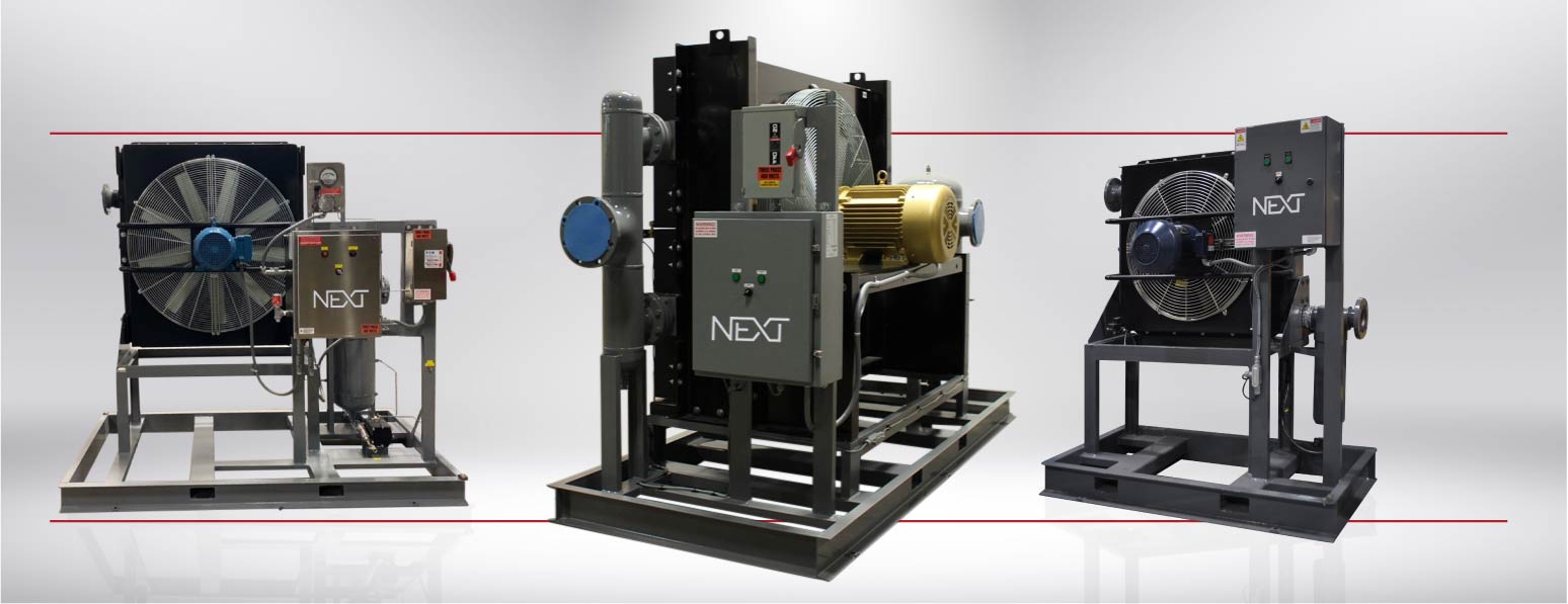
NACA Series (130-4,500 CFM)
Air Cooled Aftercoolers
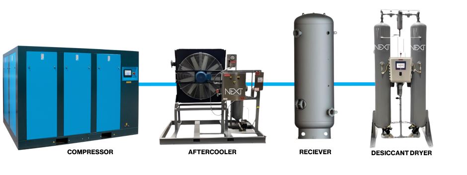
Next’s NACA packaged series aftercoolers use ambient air to cool the hot air leaving an air compressor ( typically 180 ° F to 300 ° F) to usable levels (100 ° F to 115 °F). An aftercooler can remove as much as 60% of the water vapor in compressed air condensation that would otherwise flood the piping system downline. As the air cools, the water vapor present condenses into liquid water, which should be removed with a moisture separator. Aftercoolers can be sized to cool the compressed air within 5 ° F to 20 ° F of the ambient air temperature approach . For example, with 90 °F ambient air temperature, compressed air can be cooled to 105 ° F. An aftercooler can reduce the size of dryer necessary to meet system output air requirements, will extend the life of dryer and filters, and reduce maintenance, making it an outstanding value!
The NACA Series represents a high-quality solution to easily remove water vapor and to cool compressed air to safe usable levels for many industrial applications. NAC coolers can be used when cooling water is not available, limiting costs and plant complexity and can prepare the air for further filtration and drying.
NACA coolers can be installed immediately downstream of compressors or blowers remove up to 60% of the condensate, protecting the entire compressed air system or production process. A high-quality aftercooler, properly sized, is an excellent investment that can help ensure that the compressed air system works efficiently, thereby guaranteeing the quality of the finished product.
Advantages & Benefits
- Significant energy and capital investment savings
- Optimized compressed air systems performance
- Reduced maintenance and improved product quality
- Reliability and continuous operation
- Very low pressure drops with optimum cooling performances
NACA Standard Features
- Advanced technology designs to maximize heat transfer.
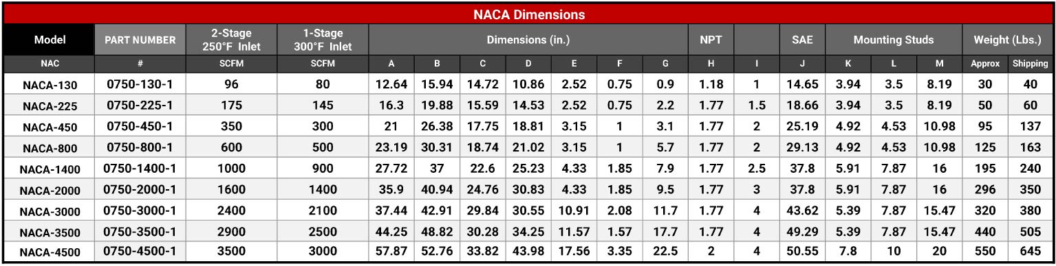
- Sizes from 130 to4500 cfm ( at 250 ° F inlet and 5° to 20 ° F approach temperature)
- Durable aluminum plate core design saves space and minimizes energy usage
- Standard TEFC (Totally enclosed fan cooled motor for rough environments)
- Reduced air side fouling
- Compact design compared to conventional fan and tube design provides smaller footprint.
- Corrosion resistance construction.
- Horizontal airflow standard with vertical air flow optional.
- Rugged bar & plate designs
- Up to 60% smaller than conventional fi n and tube designs
- Robust Construction & Compact design
- Low Pressure drop design
- Protective grill from heat exchanger
- High efficiency and low noise axial fans
- Sturdy skid
- Standard protection with epoxy powder coating
- Significant energy and capital investment savings
- Optimized compressed air system performance
- Reduced maintenance and improved product quality
- Reliability and continuous operation
- Very Low pressure drops with optimum cooling performance
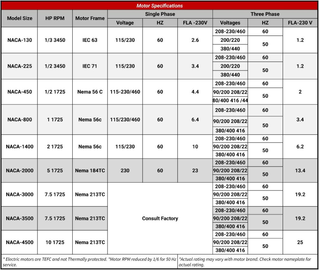
Standard Operating Voltage
- 460V / 3 PH / 60 / HZ
Electrical Certification
- UL, CUL
Maximum Working Pressure
- 250 psig.
- 17 bar.
Maximum Working Temperature
- 250 ° F
- 121 ° C
Materials
- Cooler: Aluminum
- Shroud : Powder Coated Painted Steel
- Fan Guard: Zinc Plated Steel
- Fan Blade: Polypropylene
- Blades: Aluminum Hub
- Mounting Brackets: Powder Coated Painted Steel
Flow Rate
- 130 to 4,500 cfm
Connection Type
- 1” to 2” NPT (NAC-130 to 450)
- 3” to 6” FLG (NAC-800-4,500)
Noise Level
- 85 dBA (Standard NACA-series)
- 44.1 to 73.0 dBA (depending on model)
Cooling
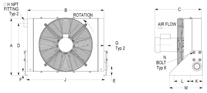
Air
Dimensions
Sizing
Recommendations are based on the following:
Heat Removal: Aftercooler = compressor Horsepower x 1.15 ( Motor Service factor) X .17
(this assumes 17% of input horsepower is rejected to heat)
15°F approach temperature: compressor air outlet temperature – ambient air temperature
Temperatures : ambient air temperature + 15°F = compressed air outlet temperature
Flows : compressor horsepower x 4.5 = scfm flow
all flow rates are based on less than a 4-psi pressure drop @ 100 psi opera ng and 100°F ambient and 50% relative humidity
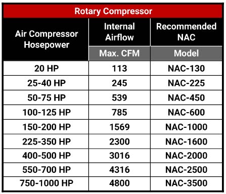
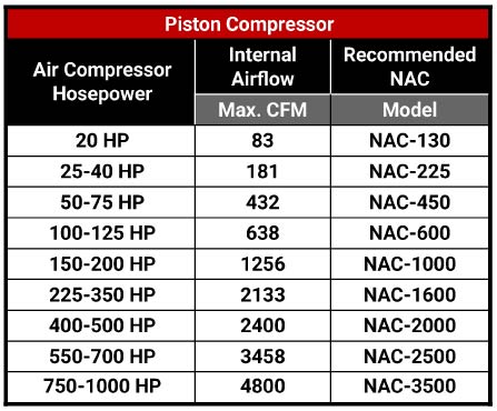
Selection
The NACA series is a complete aftercooler system designed to work on most compressors. To select the appropriate model, simply determine the compressor horsepower and select the model from the chart below.
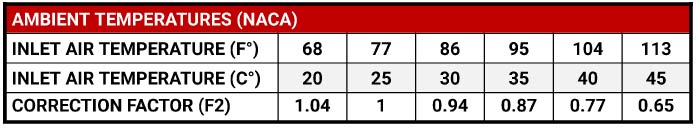
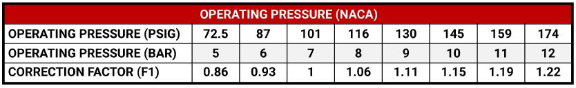
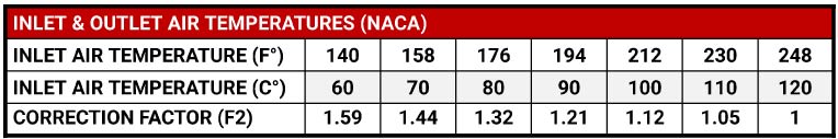
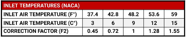
Correction Factor
NACA Optional Features
Optional FEATURES
(If an option is not listed, please contact our sales team to accommodate any additional options.)
Optional Features- TAB
ALTERNATE VOLTAGES:
- ALT-V-1: 208-230 VOLTS / 1 PHASE / 50-60 HZ
- ALT-V-2: 575 Volts / 3 PHASE / 60 HZ
ELECTRICAL ENCLOSURE:
- N4: NEMA 4: Electrical Enclosure
- N4X: NEMA 4X: Stainless Steel Electrical Enclosure
- N7: NEMA 7 Explosion Proof Electrical Enclosure
CONDENSATE DRAIN:
- EFD:External Float Drain
- EZLD:Electronic Zero Loss Drain
- PZLD:Pneumatic Zero Loss Drain
- HPTD:High Pressure Timer Drain
Separators
- Cyclone Separator
- ASME Cast Iron Separator
Electrical
- Fusible Disconnect
- Fan Cycle Switch
- Remote Start / Stop
- Fan Cycle Temp Controller
Packages
- Low Ambient Package
- Subzero Package
- Explosion Proof Package
- Low Noise Motor Fan Cycle Temp Controller
- Heresite Protective Coating
Your next step toward working with NEXT Air & Gas is to contact us for a Quote. Fill out the information below and give us the appropriate information needed to get started. Be sure to fill out all the contact information and our team will reach out with any questions or concerns.
If you’d rather speak to Sales Engineering, feel free to contact us at (865) 635-8178.
Below are links to product information and brochures. Please click and download at your convenience. If you have any questions or suggestions on materials you think would be helpful, please call us at (865) 635-8178.
Purpose of Aftercoolers
The aftercooler is the very first air treatment component in a compressed air system. It may be integral to the compressor package or be installed post the compressor. The aftercooler performs the first step in moisture removal by lowering the compressed air temperature so that much of the water vapor ingested by the air compressor condenses. Due to this bulk moisture condensing, a liquid separator with a timed condensate drain valve is needed at or near the discharge of the aftercooler. The Aftercooler also protects downstream components from highly compressed air temperatures that may cause failures or reduce performance.
Principle of Operation
Hot compressed air passes through the NACA copper tubes. Ambient air is forced across these externally finned tubes by the use of an axial fan. Compressed air is cooled to a temperature which can be as little as 10 °C /50 °F above the ambient temperature. As the compressed air cools down, up to 80% of the water vapor condenses to a liquid and this is efficiently removed by a centrifugal separator installed at the NACA outlet.
Installation
Next aftercoolers can be installed both indoors and outdoors if the ambient temperature is between 35 °F and 104 °F .
Overview
Next Air & Gas Performance Advantages
The performance of any desiccant dryer depends on the quality of its key components. Next Air & Gas uses the best available valves, controllers and desiccant. With accurately designed and sized components, the dryers are manufactured to provide you with years of trouble-free operation.

Controls
NACA Aftercooler packages come with a durable on/off switch and temperature controller. These controls are monitored with N4 LED indicator lights.

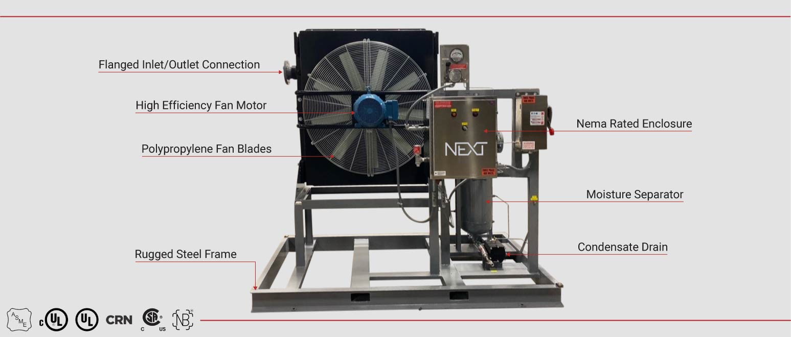
Fan Motor
- Heavy duty bearings
- Fan blade guard standard
Fan Blades
- Heavy gauge aluminum blades on steel hub
- Polypropylene blades on aluminum hub
- Blades balanced for vibration free operation.
- Fan blade guard standard

Condensate Drains
As standard all after coolers come equipped with a timed condensate drain. The timer-controlled drain incorporate a timer to discharge condensate from the separator. The timer can be adjusted to discharge the condensate at programmable intervals. automatic , mechanical and electronic zero loss condensate drains are also available.

Condenser Cooling Coils
- The NACA uses a hollow fin profile to reduce local peak strains. This way the strength of the heat exchangers is significantly increased, and their service Lifetime is considerably prolonged.
- Reduced strain: strength calculations show that when using the hollow profile maximum strain is reduced a factor of 2
- Prolonged Service Life-time: Extensive rig tests have shown that the service life-time increases by a factor ranging from 3 to 5.
- Up to 60% smaller than conventional fin and tube designs

Durable Construction Materials
- Aftercooler is mounted on rugged steel frame.
- 2-sided forklift pockets for easy transportation.
- Complies with OSHA Standards by keeping noise tolerance at <85 dBA on a time weighted average.

Flanged & NTP Connections
Connection Type
- 1” to 2 NPT (NAC-130 to 450)
- 3” to 6” FLG (NAC-800-4,500)

High Efficiency Separator
SEPARATOR
Gas, laden with moisture, enters the inlet of the separator where a deflector plate directs the flow in a downward centrifugal motion. The entrained moisture is then separated out of the flow by a reduction in velocity. The separated liquid is sent to the outer walls of the separator and falls below the re-entrainment breaker plate where it is prevented for reentering the flow stream .A dry, clean flow then results, exiting upwards through the outlet of the separator. With correct sizing and proper drainage, these separators are designed to eliminate 99% of all entrained liquids and particles that are 10 microns and larger in size. The NFS” Separators can be fabricated from carbon steel or stainless steel and are manufactured in accordance with the ASME Code Section VIII, Division I.