
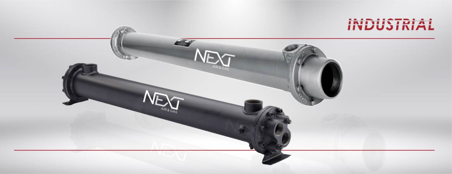
NACW Series (60-3,500 CFM)
Water Cooled Aftercoolers
The Next NACW Water Cooled Aftercooler series (60-3,500 cfm) effectively assist in maintaining trouble-free operation of compressed air equipment. By lowering the temperature of the compressed air in down stream air lines, up to 70% of the water vapor present condenses to a liquid. This is then removed by moisture separators.
Water-cooled aftercoolers can be sized as a single source cooler or as a trim cooler for use during hotter weather. By lowering the temperature of compressed air in downstream air lines, the risk of fires or explosions is reduced and the need to insulate piping is eliminated. Also, it is necessary to cool the air to a maximum of 120 ° F (49° C) before introducing it into a dryer or filter for further treatment.
Next’s water cooled after coolers consist of a shell and tube heat exchanger in which compressed air is cooled to 10 to 20 ° F ( 6 to 11 ° C) of the temperature of the cooling water in the shell. As the air cools, up to 70% of the watervapor present condenses to a liquid which can then be removed by a separator.
NACW Standard Features
- Single pass design with smooth surface copper tubes minimizes fouling and allows lower pressure drop.
- Counterflow shell and tube design provides close approach temperature; gains maximum heat removal benefit from expensive cooling water.
- Copper tubes heat exchanger surfaces provide excellent heat transfer.
- Seamless shells have maximum rupture strength and corrosion resistance.
- Can be mounted in horizontal or vertical positions.
- Tube rolled into tube sheet eliminates thermal stress.
- Removable end hoods facilitate cleaning and servicing.
- Drain ports on shell side for easy maintenance.
- Compact package provides smaller footprint.
Long Service Life
- Heat exchanger made from non-ferrous materials…eliminates rust and galvanic corrosion… reduces stress due to different rates of thermal expansion
- Seamless shells have maximum rupture strength and corrosion resistance
- Tubes rolled into tube sheet… eliminates thermal stresses of brazing
Ease of Service
- Removable end bonnets facilitate cleaning and servicing.
- Models (NACW-600+) and larger include shell side drain ports.
- Models (NACW-1000+) and larger –large 3/8” inch tubes reduce fouling are easy to clean
Easy to Install
- Compact package
- Mounting Brackets supplied as standard.
- Can be mounted in vertical or horizontal position. ( May be rotated in 90° increments.)
Rated CFM Flow
- 60 to 3500 scfm (Rotary @ 200 ° F ) Inlet
- 40 to 2800 scfm ( 2-Stage @ 250 ° F) Inlet
“Tube” Air Max Working Pressure
- 150 psig
- 11.3 bar
“Shell” Water Max Working Pressure
- 150psig
- 11.3 bar
Maximum Working Operating Temperature
- 350 ° F
- 177 ° C
Pressure Drop
- 3 psi
- .21 bar
Water Flow Rate
- 3 gpm / 100 scfm
- 11.8 1/min/3 Nm3/min
Cooling
- Air/gas to Water
Materials
- Shell : Carbon steel
- Baffles: Brass
- Tubes: Copper
- End Hubs: Carbon steel
- End Bonnets: Cast Iron
- Mounting Brackets: Powder Coated Painted Steel
- Gasket: Nitrile rubber
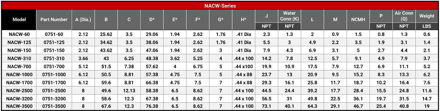
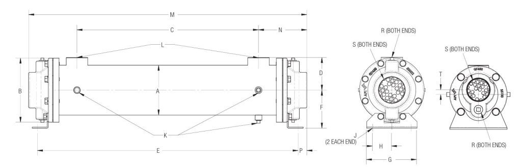
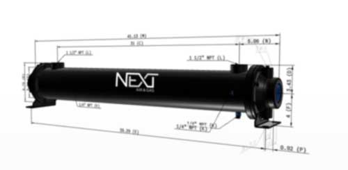
Dimensions
Capacity Selection
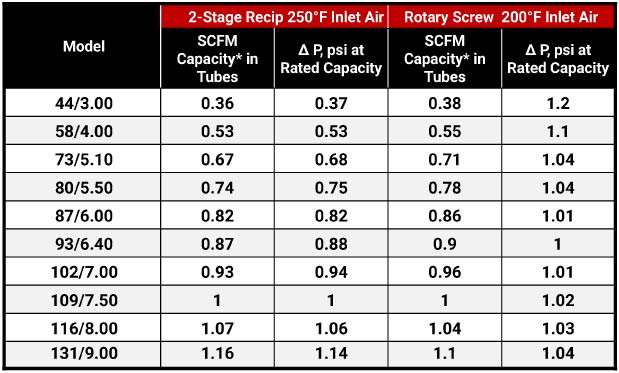
Based on ambient air 60° F , 14.7 psi, and 50% relative humidity. Compressed air cooled to within 15 °F of inlet water temperature. Water flow rate 3 GPM per 100 scfm air flow. For single stage compressor type, 300 °F inlet , use 2-stage scfm capacities with a 15% reduction.
Selection Example
Two stage compressor with a 340 SCFM air delivery at 100 PSIG and a 250 ° F discharge temperature. Maximum Allowable pressure loss is 2 PSI. Water flow rated to be determined.
Solution
- From the 2-stage compressor collum select model NACAW-700 with 440 SCFM Capacity.
- To determine Δ P : Read column to left of SCFM capacity selected . Δ P = 0.3 PSI
- Water flow rate required 340 SCFM X .03=10.2 GPM
NACW Optional Features
Optional FEATURES
(If an option is not listed, please contact our sales team to accommodate any additional options.)
Configuration
- Dual Pass
- Quad Pass
- ASME / CRN Certification
Materials
- Shell & Baffles: Stainless Steel
- Tubes: Copper Nikel , Stainless
- Bonnets: Brass, Stainless Steel
- Stainless Steel Construction
Condensate Management
Separators
- Cyclone Separator
- ASME Cast Iron Separator
CONDENSATE DRAIN:
- EFD:External Float Drain
- EZLD:Electronic Zero Loss Drain
- PZLD:Pneumatic Zero Loss Drain
- HPTD:High Pressure Timer Drain
Your next step toward working with NEXT Air & Gas is to contact us for a Quote. Fill out the information below and give us the appropriate information needed to get started. Be sure to fill out all the contact information and our team will reach out with any questions or concerns.
If you’d rather speak to Sales Engineering, feel free to contact us at (865) 635-8178.
Below are links to product information and brochures. Please click and download at your convenience. If you have any questions or suggestions on materials you think would be helpful, please call us at (865) 635-8178.
Overview
Working Principle
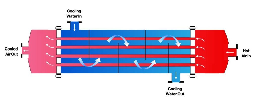
In an air-to-water application, works by transferring heat from a flowing air stream (on the shell side) to circulating water within the tubes, where the air passes over the tubes, allowing the heat to transfer through the tube walls and into the water, effectively cooling the air and heating the water; the key principle is that the two fluids flow in separate channels, with the heat exchange occurring through the tube walls, maximizing the surface area for heat transfer.
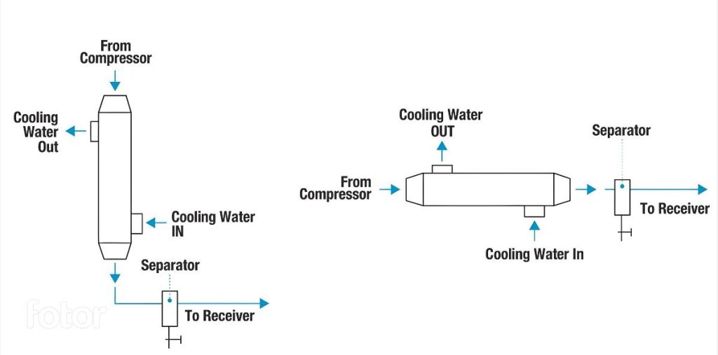
Piping Diagram
Next Aftercoolers can be mounted in either of the positions shown. Separators should be used as shown. Consult Factory for separator recommendations.
Next Air & Gas Performance Advantages
The NAC W shell and tube aftercoolers provide the best overall value and longevity. Models from 75 to 1500 scfm. single pass Next aftercoolers couped with a moisture separator provide a cost-effective means of removing harmful moisture and oil from your compressed air stream . This allows for trouble free operation of downstream equipment and air powered tools.
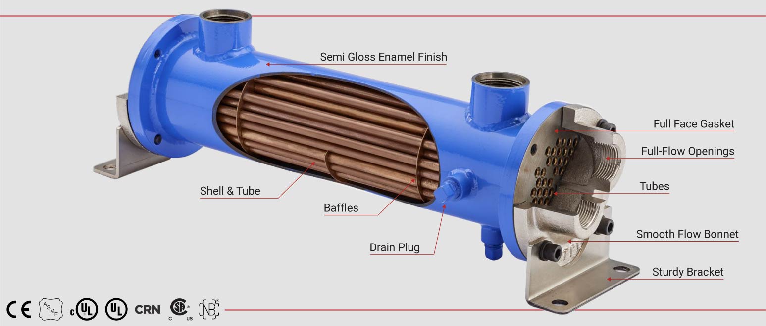
Smooth Flow Bonnet
Distributes fluid to tubes with minimum turbulence. One, two or four pass interchangeability.
Drain Plug
All water cooled after coolers except 2 inch have drain plugs.
Full Flow openings
Adequately sized for minimum pressure drop. Flexible connections are recommended when vibration is present
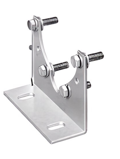
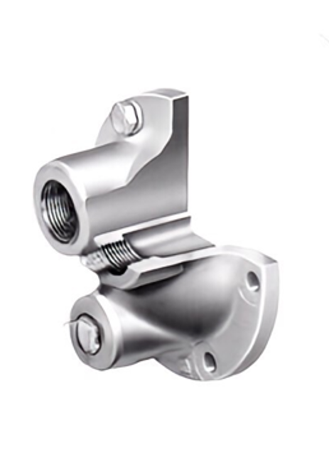
Sturdy Bracket
Made of Heavy gauge steel.. Adjustable for installation in various positions. Rotatable through 360 degrees Adequately sized for minimum pressure drop. Flexible connections are recommended when vibration is present
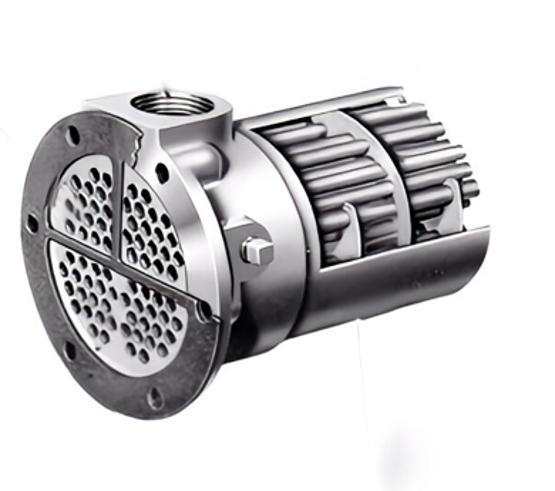
Shell & Tube Bundle Assembly
Baffles precision stamped to close tolerances. Clearances between baffles and tubes, baffles and shell are minimum to obtain maximum heat transfer. Available in various size combinations to suit heat transfer requirements.
Full Face Gasket
Bonded gasket for maximum pressure & temperature.
Tubes
Adequately High temperature boned into tube sheets. On other models’ tubes are rolled into tube sheets by electronic control.
End Hub
End hub is high quality forging or casting. Full flow opening is designed for minimum pressure drop.
Baffles
Segmented baffles available in five spacings for maximum heat transfer with minimum fluid pressure drop.
Finish
Single coat of grey or black, semi-gloss enamel paint suitable for outdoor duty in non-critical applications, and as a base for subsequent coats for severe duty or extended life.
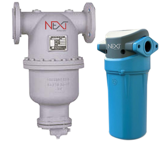
High Efficiency Separator
Gas, laden with moisture, enters the inlet of the separator where a deflector plate directs the flow in a downward centrifugal motion. The entrained moisture is then separated out of the flow by a reduction in velocity. The separated liquid is sent to the outer walls of the separator and falls below the re-entrainment breaker plate where it is prevented for reentering the flow stream .A dry, clean flow then results, exiting upwards through the outlet of the separator.
With correct sizing and proper drainage, these separators are designed to eliminate 99% of all entrained liquids and particles that are 10 microns and larger in size. The NFS separators can be fabricated from carbon steel or stainless steel and are manufactured in accordance with the ASME
Code Section VIII, Division I.

CONDENSATE DRAINS
The remaining humidity in compressed air turns into water as the air cools while it moves through the system. Because water causes corrosion and damage, drains must be installed throughout your network. Next has a range of drains, automatic or electronic, and timed, that will keep your aftercooler, working optimally.
DURABLE Construction
- Heat exchanger tubes made from nonferrous material eliminates rust, galvanic corrosion, and reduces stress due to different rates of thermal expansion.
- Seamless shells have maximum rupture strength and corrosion resistance
- Tubes rolled into tube sheet eliminated thermal stresses from brazing